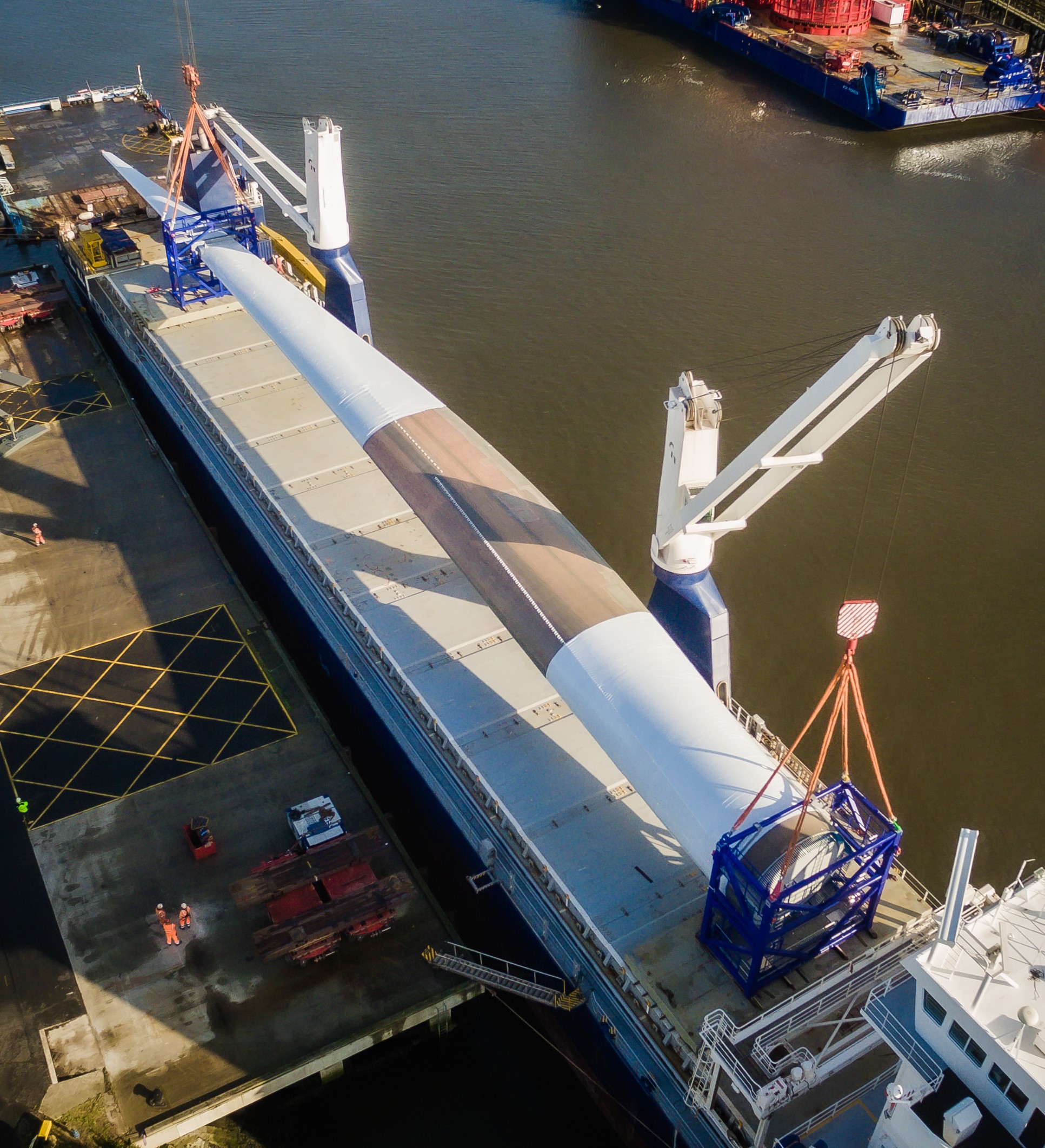
Function
The rotor extracts kinetic energy from the air and converts this into rotational energy in the drive train.
What it costs
About £6 million for a 15 MW floating offshore wind turbine.
Who supplies them
Wind turbine rotors are usually designed and supplied by the wind turbine supplier as part of the complete wind turbine. Independent blade manufacturers are used by some wind turbine suppliers.
Key facts
A rotor for a 15 MW turbine has a mass of about 230 t and a diameter of about 224 m.
The rotor consists of blades, a hub casting, blade system, bearings, and pitch system.
Blades are typically made from fibreglass and epoxy resin. There are variations between designs, with some using carbon fibre and others using polyester resins. New resin systems are being developed and tested to enable the recovery and reuse of blade materials at the end of life.
Higher tip speeds typically lead to more efficient energy capture, and tip speeds offshore are higher than those used onshore, but these are limited by design to avoid blade leading edge erosion. This is where repeated impact by raindrops, particulate matter, hail, ice, and salt erodes the blades, causing surface roughness and change in aerodynamic shape to the outer part of the blade’s leading edge. This reduces the performance of the blade and increases its sound emissions. If left unrepaired, the damage will continue until it affects the structural integrity of the blade.
Reducing the risk of leading edge erosion is an important focus for innovation. One approach is developing better coatings. Another is to incorporate leading edge protection plates similar to those used in helicopter blades that are flexible enough to cope with the deflections seen in wind turbine blades.
Each blade is bolted to a blade bearing that is bolted to a central hub on the main shaft. The blade bearing enables the pitch mechanism to adjust the blade pitch angle to control power output from the turbine, minimise loads and start or stop turbine as required.
Each blade has its own independent pitch system that allows the turbine to be controlled should one pitch system fail. Pitch systems are either hydraulically or electrically operated, with little external difference in functionality.
Typically, the blade pitch angle is adjusted almost constantly in medium-to-high winds to regulate rotor speed while the turbine is extracting maximum (rated) power. In lower winds, the pitch system operates to maximise aerodynamic efficiency, which requires substantially less movement.
There is potential for larger offshore wind rotors, though for the same design, mass increases faster than the additional energy generated. This is because energy capture is proportional to the two-dimensional swept area (square of blade length), but the blades increase in size and mass in three dimensions (cube of blade length). Substantial improvements in blade technology have kept the actual increase in mass nearer the square than the cube of blade length as wind turbines have increased in size.
Capacity factors of over 50%, are expected for 15 MW offshore turbines on good offshore sites. This compares with capacity factors of about 40% for good onshore sites.
As turbine rotor diameter increases, with the same limit on tip speed, the rotational speed decreases. Lower rotational speeds make it more difficult to design a support structure that avoids resonant frequencies excited by loading from waves and operation of the turbine itself.
Rotor speeds are 4 to 8 r/min, resulting in a maximum tip speed of over 100 m/s.
In the UK, rotor clearance must be at least 22 m above mean high water spring (MHWS) tides.
There are no major differences in the rotors designed for floating or fixed offshore wind farms.
What’s in it
- Blades
- Blade system and bearings
- Hub casting
- Pitch bearing and actuator system
- Rotor auxiliary systems
